Induction Motor
An induction motor or asynchronous motor is an AC electric motor in which the electric current in the rotor needed to produce torque is obtained by electromagnetic induction from the magnetic field of the stator winding. An induction motor can therefore be made without electrical connections to the rotor. An induction motor's rotor can be either wound type or squirrel-cage type.
Three-phase squirrel-cage induction motors are widely used as industrial drives because they are self-starting, reliable and economical. Single-phase induction motors are used extensively for smaller loads, such as household appliances like fans. Although traditionally used in fixed-speed service, induction motors are increasingly being used with variable-frequency drives (VFDs) in variable-speed service. VFDs offer especially important energy savings opportunities for existing and prospective induction motors in variable-torque centrifugal fan, pump and compressor load applications. Squirrel cage induction motors are very widely used in both fixed-speed and variable-frequency drive (VFD) applications.

Fig 1. Induction Motor
Principle of operation : -
In both induction and synchronous motors, the AC power supplied to the motor's stator creates a magnetic field that rotates in synchronize with the AC oscillations. Whereas a synchronous motor's rotor turns at the same rate as the stator field, an induction motor's rotor rotates at a somewhat slower speed than the stator field. The induction motor stator's magnetic field is therefore changing or rotating relative to the rotor. This induces an opposing current in the induction motor's rotor, in effect the motor's secondary winding, when the latter is short-circuited or closed through an external impedance. The rotating magnetic flux induces currents in the windings of the rotor, in a manner similar to currents induced in a transformer's secondary winding(s).
The induced currents in the rotor wingdings in turn create magnetic fields in the rotor that react against the stator field. Due to Lenz's Law, the direction of the magnetic field created will be such as to oppose the change in current through the rotor winding. The cause of induced current in the rotor windings is the rotating stator magnetic field, so to oppose the change in rotor-winding currents the rotor will start to rotate in the direction of the rotating stator magnetic field. The rotor accelerates until the magnitude of induced rotor current and torque balances the applied mechanical load on the rotation of the rotor. Since rotation at synchronous speed would result in no induced rotor current, an induction motor always operates slightly slower than synchronous speed. The difference, or "slip," between actual and synchronous speed varies from about 0.5% to 5.0% for standard Design B torque curve induction motors. The induction motor's essential character is that it is created solely by induction instead of being separately excited as in synchronous or DC machines or being self-magnetized as in permanent magnet motors.
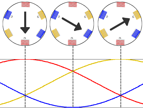
Fig 2. Three-phase power supply provides a rotating magnetic field in an induction motor
Synchronous speed: -
,

An AC motor's synchronous speed, , is the rotation rate of the stator's magnetic field,

where is the frequency of the power supply, is the number of magnetic poles, and is the synchronous speed of the machine. For in Hertz and in RPM.


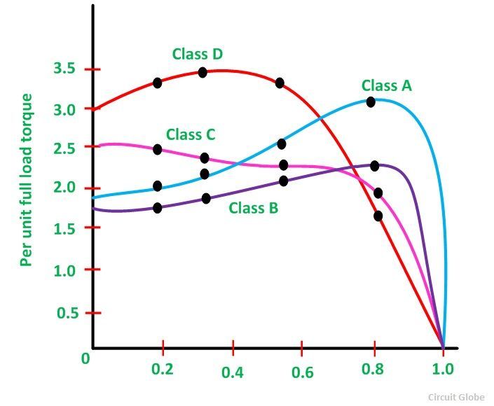
The speed torque characteristics of Cage Induction Motor of various Classes are shown below : -
Class A Motors : -
Class A motors have normal starting torque, high starting current and low operating slip (0.005-0.015). The design has low resistance single cage rotor. The efficiency of the motor is high at full load. Applications of Class A motors are fans, blowers, centrifugal pumps, etc.
Class B Motors : -
Class B motors have normal starting torque, low starting current and low starting current and low operating slip. The motor is designed, in such a way to withstand the high leakage reactance, as a result, the starting current is reduced. The starting torque is maintained by use of a double cage or deep bar rotor.
The Class B motors are most commonly used motor and used for full voltage starting. The applications and the starting torque are same as that of Class A motors.
Class C Motors : -
The class C motors have high starting torque and low starting current. Such motors are of the double cage and deep bar and has higher rotor resistance. The loads are compressors, conveyors, reciprocating pumps, crushers, etc.
Class D Motors : -
Class D motors have the highest starting torque as compared to all the other class of motors. The bars of the rotor cage are made up of brass. These types of motors have low starting current and high operating slip. The value of full load operating slip varies between 8 to 15%. Thus, the efficiency of the motor is low.
These motors are suitable for driving intermittent loads which require frequent acceleration and high loads. For example – punch presses, bulldozers and die stamping machines. When the motor is driving the high impact loads, it is coupled to a flywheel to provide kinetic energy.
Applications of Polyphase Wound Rotor Induction Motors : -
- Wound rotor motors are suitable for loads requiring high starting torque and where a lower starting current is required.
- The Wound rotor induction motors are also used for loads having high inertia, which results in higher energy losses.
- Used for the loads which require a gradual buildup of torque.
- Used for the loads that require speed control.
- The wound rotor induction motors are used in conveyors, cranes, pumps, elevators and compressors.
- The maximum torque is above 200 percent of the full load value while the full load slip may be as low as 3 percent. The efficiency is about 90 %.

Comments
Post a Comment